Pump Variable Frequency Drives: Why Do Seals Fail When the Pump Runs Too Slow?
It is well documented that varying the speed of a pump to meet part-load conditions is a great way to save energy. The savings occur due to the Third Pump Affinity Law, which states that the power consumption of a pump varies with the CUBE of the speed reduction. The actual reduction achieved in an installed system may be somewhat less, though still VERY significant (to determine actual savings requires a knowledge of the application’s “system curve,” a topic covered in one of our FH Institute hydronic courses). Note 1
While speed reduction is a great thing for energy savings, TOO MUCH speed reduction results in rapid failure of the pump’s mechanical seal. To understand exactly why, we must understand something called hydro-dynamic forces. Let’s start by reviewing the construction of a typical mechanical seal.
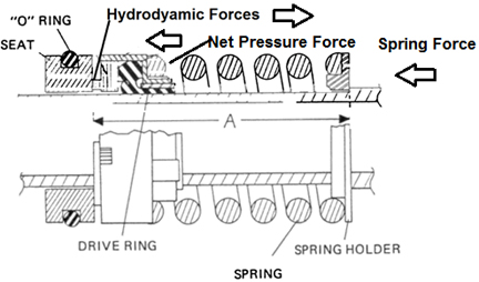
As shown in this figure, a seal consists of a stationary element, the seat, which is pressed into a machined cavity in the pump casting and held by an “O” ring, and a rotating element, which is pressed onto the pump shaft,Note2 and held in place by an elastomer drive ring. Note the face of the rotating element is normally a softer material than the face of the seat, and that both faces are manufactured to be flat to within very fine tolerances.
In operation, several forces act to maintain a very small gap between the faces of the rotating element and the stationary element. The gap fills with system fluid (usually water or glycol in HVAC systems), which lubricates the seal faces, preventing overheating and failure, which would occur with direct face-to-face contact and rotation. Yet the gap is small enough that any leakage should be undetectable. The forces that create this gap include:
- A force created by pressure in the pump acting on the back (right) side of the rotating element, somewhat counterbalanced by the same pressure acting on the smaller surface “front” surface of the rotating element. The net effect is to push the rotating element toward the seat.
- A pressure force in the gap created by pressure in the casing acting on the inner rim of the rotating element as it “attempts to escape” to atmospheric pressure. It acts to separate the seal surfaces.
- Spring force. The spring provides resilience in the seal system and acts to maintain the gap between the fixed and rotating elements as the seal faces erode. It pushes the rotating element toward the seat.
- A “hydro-dynamic” force, which forms when the shaft rotates, acts to push the rotating element away from the seat. Though hydro-dynamic forces are not completely understood, they are thought to consist of: (a) Centrifugal force, caused by fluid that spins outward between seal faces during rotation, and (b) A wave-like action that forms in the fluid between the seal faces. This wave is thought to be created, during rotation, by minor surface irregularities in the “flatness” of the faces. This wave action creates a force that separates the faces.
Under normal operation, the seal is designed so that the forces resolve to maintain just the right amount of gap for the application – enough that seal face lubrication is maintained, but small enough to prevent detectable leakage.
Though we don’t completely understand the mechanism of hydro-dynamic forces, we know that they increase with increasing shaft speed and decrease with decreasing shaft speed.
Q: So, what causes the seal to wear rapidly of speed is too low?
A: All seals wear OVER TIME. But when shaft speed slows excessively, the hydro-dynamic forces decrease to the extent that the seal faces either actually touch, or become so close that excess heat is generated. Either event causes rapid seal wear.
Q: So, what is the solution?
A: The answer is to maintain a minimum RPM that is high enough to create hydro-dynamic forces sufficient to maintain a “healthy” seal gap. As you might imagine, every pump, every seal, every application is different, so we are left with rules of thumb that have proven to be relatively “safe.”
Note 3
| Motor/Pump Nominal RPM | Min. Allowable Speed | Min. Drive HZ |
| 1200 | 500 | 25 |
| 1800 | 450-600 | 15-20 |
Note that many pump applications serve systems with significant static head, or systems where a pressure set-point must be maintained. In most of these systems, a slower speed than the recommended minimum may never occur. The pumps need to rotate at a higher speed than the minimums stated in order to meet the pressure requirements. But in other applications, (a variable speed boiler secondary pump is a good example), where no minimum head requirement exists, pumps COULD be called upon to operate at very low speeds. To be safe, in ALL applications, the recommended solution is to program a minimum speed into the variable frequency drive that meets the values above.
Q: Are there other considerations with variable speed pumps?
A: Maybe so. It stands to reason that, over time, the seal faces will likely operate with a smaller gap than in a fixed-speed application. It seems logical that finer particles of scale and iron oxide would, then, cause grooves in the seal, particles which may not be a problem with a bit wider gap. Though we have read of no specific studies, it does make extra sense to strive for system cleanliness. It would be beneficial, in the interest of extending seal life, to install an air/dirt separator (similar to the Taco 4900) plus a bypass filter in the system.
In summary, it is important to understand the role of hydro-dynamic forces in pump application and that they affect the minimum recommended pump speed.
Notes:
Note 1: See the FH Institute page for upcoming and correspondence courses.
Note 2: Most commercial pumps actually are equipped with a non-corrosive shaft sleeve that is pressed over the actual pump shaft. The rotating element is pressed onto this sleeve.
Note 3: These recommendations are based on pump considerations. Motor & drive limitations MAY be higher. Check with manufacturers of those devices.